| MICA HEATER
BANDS Standard or Advantage Thin! |
| BASIC CONSTRUCTIONS "Advantage Thin Line" Mica Bands These Heaters were designed primarily as economical mica band heaters in nozzle and narrow width sizes. In the range of sizes recommended in our price list these heaters will perform as well as any mica band currently available. Although these heaters can be made in sizes other than those listed, Omega's standard line of mica bands are recommended for larger size heaters as well as higher temperature and high voltage applications. |
TYPE1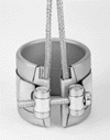 BARREL NUT STRAP LEADS IN METAL BRAID exit through edge on both sides on both sides of gap. |
|
TYPE 2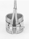 BARREL NUT STRAP LEADS WITHOUT METAL BRAID exit through edge on both sides of gap. |
TYPE 3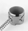 BARREL NUT STRAP LEADS exit through outside surface of heater. Options A,B,D. Options "A" (Armor) is shown. |
TYPE 4 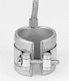 BARREL NUT STRAP LEADS exit through edge, 180 deg. From gap. This construction not recommended for bands under 2" wide. Options B,C, Option "B" (Braid) is shown. |
TYPE 5 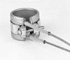 BARREL NUT STRAP LEADS exit through edge, inside gap, one from each side of gap. Suggested for use on small diameter bands where leads are not subjected to strain or plastic drool. Option C only. |
TYPE 6 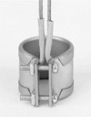 FLANGE
LOCK-UP LEADS exit through edge on both sides of gap.
Option B,C. This construction available, but not
recommended. Use of Type 1 or 2 is suggested. FLANGE
LOCK-UP LEADS exit through edge on both sides of gap.
Option B,C. This construction available, but not
recommended. Use of Type 1 or 2 is suggested. |
TYPE 7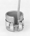 BARREL NUT BARREL NUTSTRAP LEADS IN METAL BRAID exit through edge, both leads at same side of gap. |
TYPE 8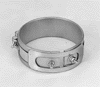 BARREL NUT STRAP - ONE PIECE POST TERMINAL at each end of heater. |
TYPE 9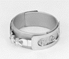 BARREL NUT STRAP - TWO PIECE POST TERMINAL at each end of heater. |
TYPE 10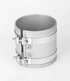 BARREL NUT STRAP - ONE PIECE POST TERMINALS at same end of heater. This terminal arrangement suggested for bands 3" or more in width. |
TYPE 11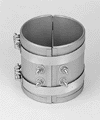 BARREL NUT STRAP - TWO PIECE POST TERMINALS at same end of heater. |
TYPE 12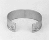 BARREL NUT STRAP-EXPANDABLE Options A, B, C, P. Option "P" (Post Terminal) is shown. |
TYPE 13 BARREL NUT STRAP PARTIAL COVERAGE band with padded clamping straps. Options A, B, C, P. Option "p" (Post Terminal) is shown. |
TYPE 14 FLANGE LOCK-UP ONE PIECE LEADS exit through outside surface of heater . Options A, B, C. Option "A" (Armor) is shown. |
TYPE 15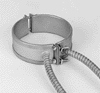 FLANGE LOCK-UP- TWO PIECE LEADS exit though outside surface of heater. Options A, B, C. |
TYPE 16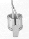 TAPERED WEDGE LOCK LEADS exit through edge. Options B, C,. Option "C"(Flexible Leads) is shown. |
TYPE 17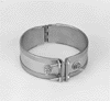 FLANGE LOC-UP-HINGED POST TERNIMAL at each end of heater. |
TYPE 18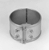 FLANGE LOCK-UP-HINGED POST TERMINALS at same end of heater. Terminals are normally located near hinge - unless otherwise specified. |
TYPE 19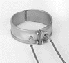 FLANGE
LOCK-UPHINGED LEADS exit through outside surface of bank.
Options A, B, C. Leads are normally locate near hinge -
unless otherwise specified. Option "C" is
shown. FLANGE
LOCK-UPHINGED LEADS exit through outside surface of bank.
Options A, B, C. Leads are normally locate near hinge -
unless otherwise specified. Option "C" is
shown. |
TYPE 20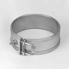 FLANGED LOCK-UP-ONE PIECE POST TERMINAL at each end of heater. |
TYPE 21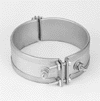 FLANGED LOCK-UP-TWO PIECE POST TERMINAL at each end of heater. |
TYPE 22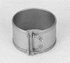 FLANGED LOCK-UP-ONE PIECE *POST TERMINAL at same end of heater. |
TYPE 23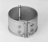 FLANGED LOCK-UP-TWO PIECE *POST TERMINALS at same end of heater. |
TYPE 24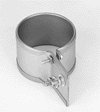 EXTENDED FLANGED WITH ELECTRICAL CONNECTIONS-ONE PIECE. Options A, B, C, P. |
TYPE 25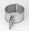 EXTENDED FLANGE WITH ELECTRICAL CONNECTIONS - TWO PIECE. Options A, B, C, P. |
TYPE 26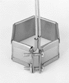 HEXAGONAL BAND HEATER Lead arrangement shown is suggested. |
TYPE "S"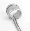 OMEGA’S PATENTED PREMIUM NOZZLE HEATER RESISTS PLASTIC DROOL RUGGED CONSTRUCRTION HIGHER WATT DENSITY |
BARREL NUT SIZES Standard Barrel Nuts (3/8" high) are normally supplied on bands 1-1/2" ID and over. Low profile Barrel Nuts (7/32" high) are normally supplied on bands under 1-1/2" ID |
| *ON FLANGED BANDS, when post terminals are specified at the same end of band, they will normally be located as follows: Bands under 2" wide-Post terminals will be placed tandem, around circumference of band. Bands 2" wide and over-Post terminals will be placed across width of band. | ||
|
WHEN ORDERING PLEASE SPECIFY: 1. QUANTITY |
||||